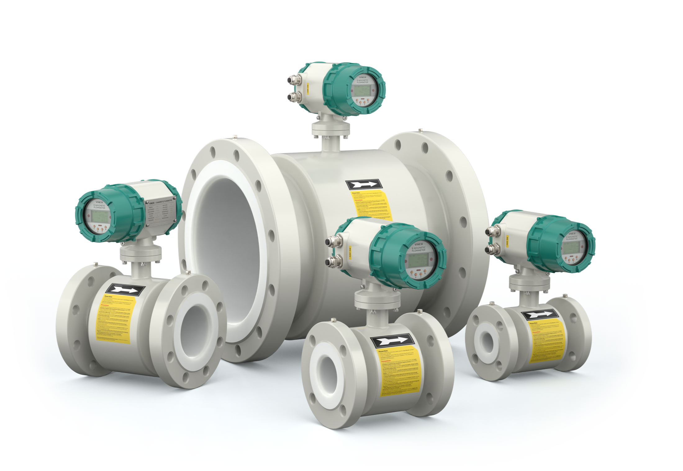
MWDC-LDG series
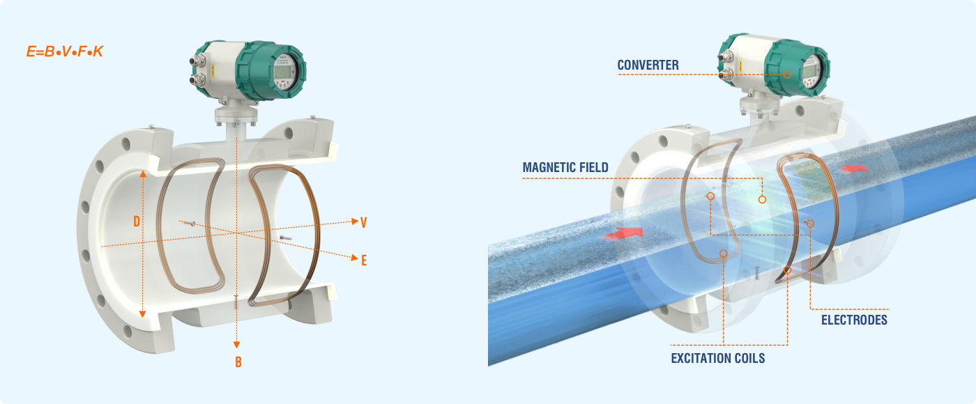
An electromagnetic flowmeter consists of two main components: the sensor and the converter. This device functions on the basis of Faraday's law of electromagnetic induction and is used to measure the flow of conductive liquids.


An electromagnetic flowmeter consists of two main components: the sensor and the converter. This device functions on the basis of Faraday's law of electromagnetic induction and is used to measure the flow of conductive liquids.


An electromagnetic flowmeter consists of two main components: the sensor and the converter. This device functions on the basis of Faraday's law of electromagnetic induction and is used to measure the flow of conductive liquids. It is widely used across various industries, including metallurgy, chemical, paper and pulp, environmental protection, petroleum, textile, food and beverage, municipal management, and water conservancy construction.
The sensor generates a magnetic field, which induces a voltage in the conductive liquid, while the converter converts the voltage signal into a flow rate. As a result, the electromagnetic flowmeter provides accurate and reliable readings, enabling precise measurements in various industrial applications.

The electromagnetic flowmeter uses Faraday's Law of electromagnetic induction to measure the process flow. When an electrically conductive fluid flows in the pipe, an electrode voltage E is induced between a pair of electrodes placed at right angles to the direction of magnetic field. The electrode voltage E is directly proportional to the average fluid velocity V.
The sensor is designed to perceive induced electrode voltage E as an indication of flow and relay this signal to the converter. Upon receipt, the converter amplifies the signal, converts it into a digital format, and filters it to eliminate noise. The resulting data is processed digitally and displayed on a backlit dot-matrix LCD screen as instantaneous flow and cumulative flow.
Furthermore, the converter boasts a 4-20mA output, an alarm output, and a frequency output. In addition, it is equipped with communication interfaces such as RS-485 and supports the HART and MODBUS protocols.


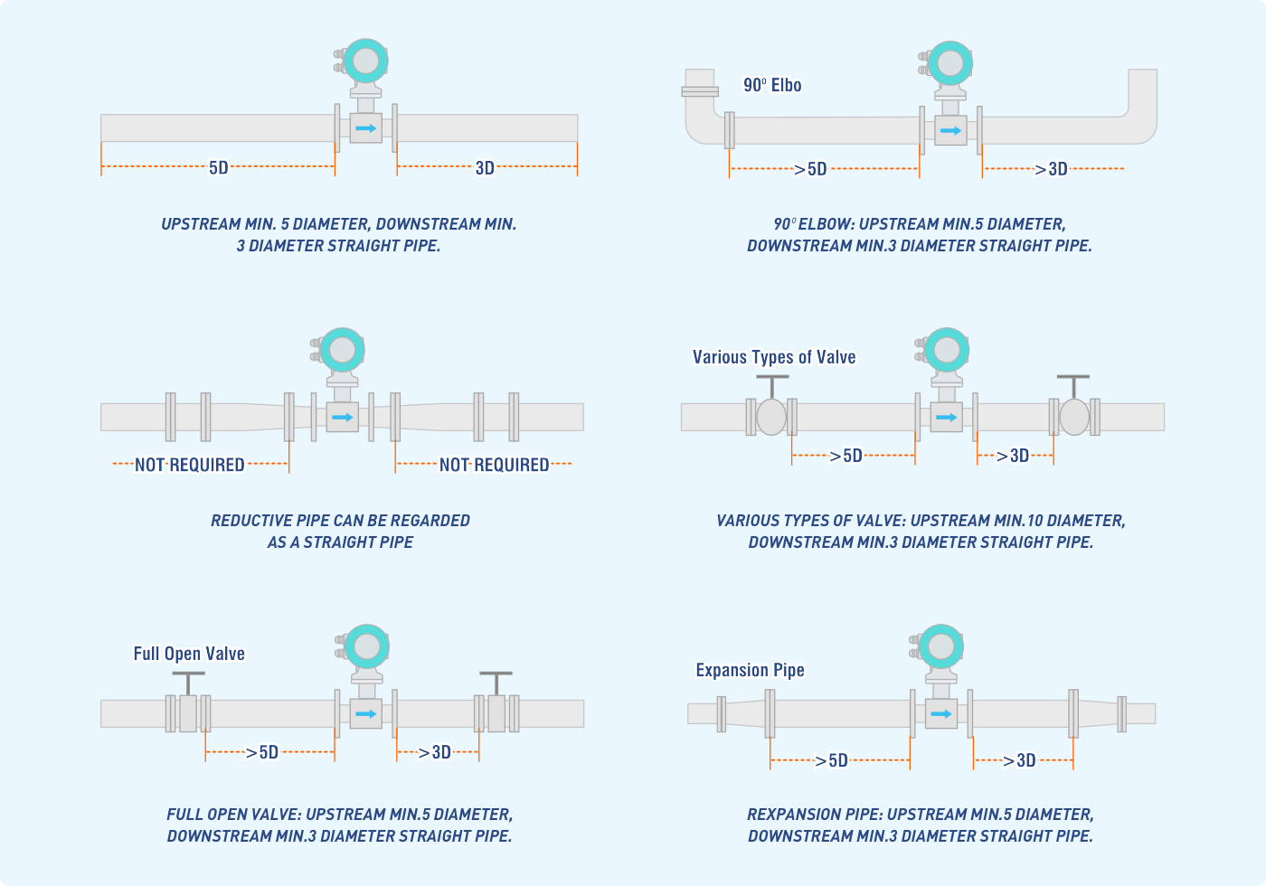
Avoid installing any objects near the flow tube that may interfere with its magnetic field, induce signal voltage, or disrupt its flow field distribution.